Grounding and Bonding: What It Actually Looks Like in Practice
Placeholder — not yet a full article, but the core comparison is now built out. Matthew has real, practical examples of grounding and bonding to build this out with further — planned as a hands-on, real-world companion to the theory (not just the code-book definitions of “grounding” and “bonding,” but what correct and incorrect implementations actually look like in practice). A relevant real source already bookmarked: pages on grounding from the ANSI/IEEE Std 142-1982 “Green Book.” Planned cross-post: once built out further, this is intended to also live at ae4jc.com, not just here — check back on both sites.
Comparison: three kinds of “ground”
The word “ground” gets used for at least three genuinely different things in an HF station, and treating them as interchangeable is where a lot of real problems start:
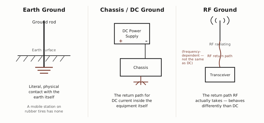
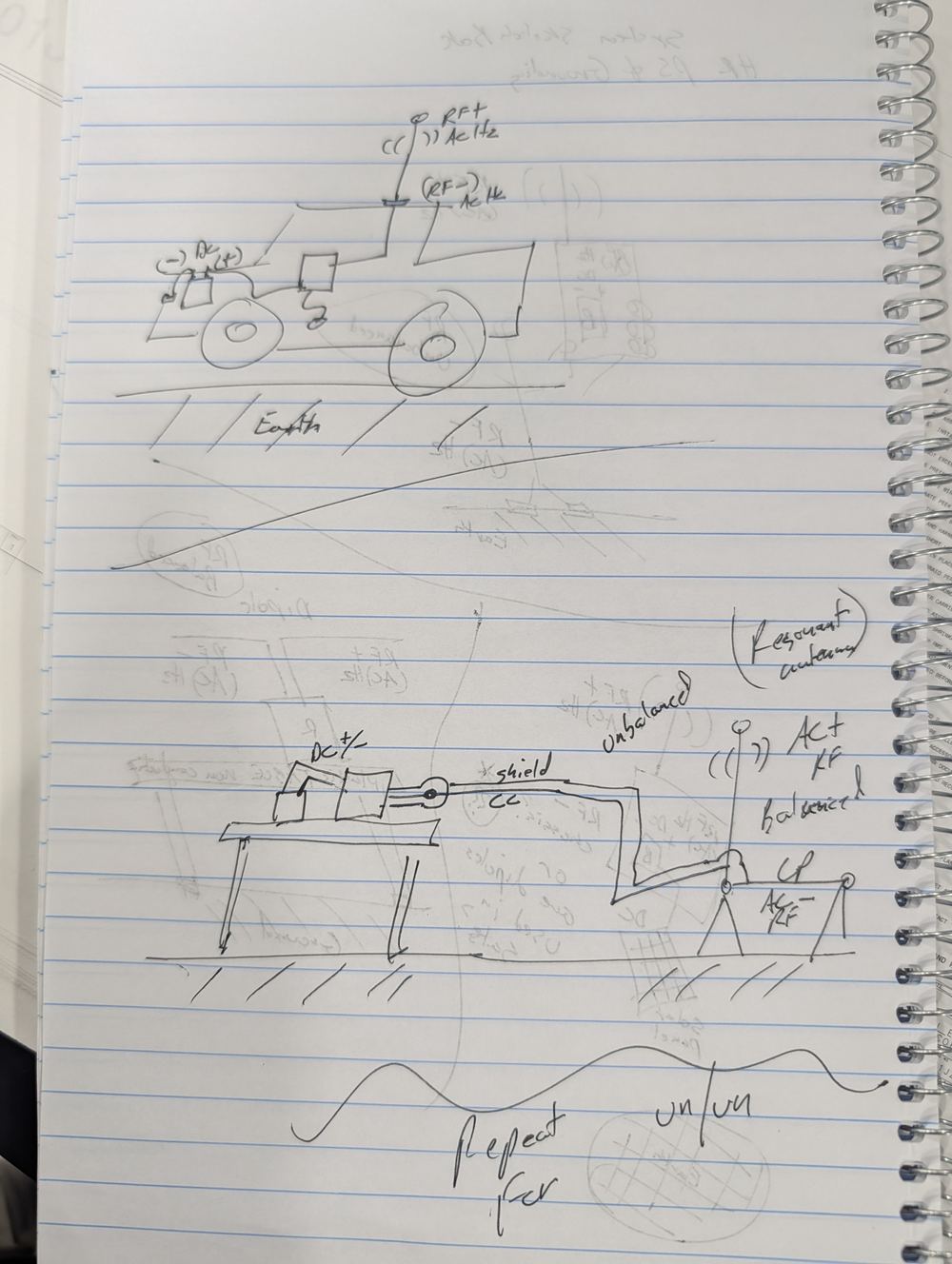
Earth ground is literal, physical contact with the earth itself — a ground rod driven into the soil. A mobile station sitting on rubber tires simply doesn’t have this, no matter how well-grounded the equipment inside the vehicle is. Chassis/DC ground is the return path for DC current inside the equipment — the power supply’s negative terminal tied to the case. RF ground is the return path RF current actually takes at HF frequencies, which behaves very differently from DC (frequency-dependent, reactive, not just resistive) — this is the one most often confused with the other two, and confusing it is a common real source of “RF in the shack” problems: hot mics, RF burns on the case, distorted audio.
Comparison: balanced vs. unbalanced RF feed
The other core distinction in the notes is how an antenna’s feedpoint relates to ground at all:
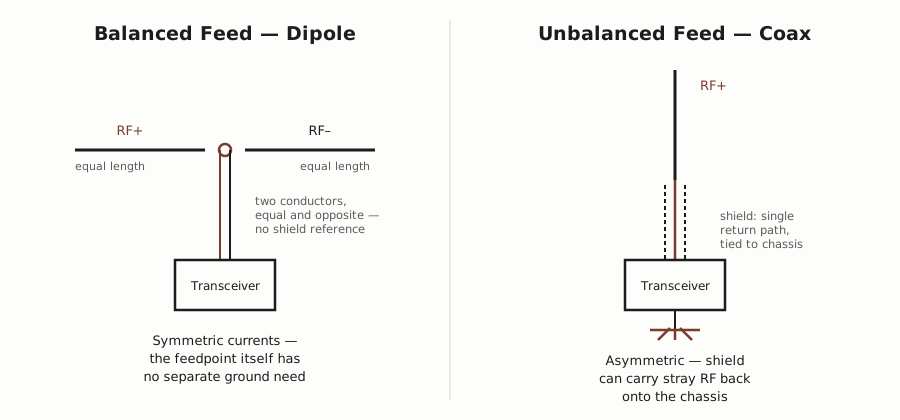
A dipole is inherently balanced: two equal-length conductors carry equal and opposite RF current, and the feedpoint itself has no separate ground reference to get wrong. A coax-fed antenna (a vertical, a whip, anything fed against a single conductor plus shield) is inherently unbalanced — the shield is both the RF return path and, usually, tied directly to the chassis, which is exactly how stray RF ends up riding back onto the equipment case if the system isn’t managed well (this is what the resonant-coupling and choke sketches in Matthew’s own notes below are addressing).
Comparison: why loop-fed antennas are quieter than open-ended ones
A related, practical question: why do loop-fed (magnetic loop) antennas so often sound noticeably quieter than open-ended wire antennas (dipoles, end-feds) on receive, even before any signal processing? Four real, distinct mechanisms are behind it, not just one:
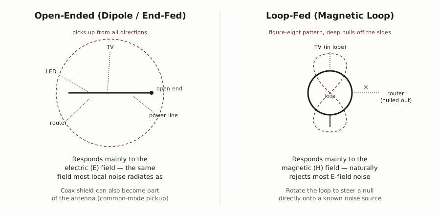
- E-field rejection. Most man-made noise — televisions, power lines, LED lighting, switch-mode supplies — radiates predominantly as an electric (E) field. Open-ended wire antennas are highly sensitive to E-fields and pick this noise up efficiently. A loop antenna instead responds primarily to the magnetic (H) field component of a radio wave, which largely sidesteps that noise before it ever reaches the receiver.
- Rejection of feedline common-mode pickup. On a typical dipole or vertical, the coax shield can become an unintentional part of the antenna system — as it routes through a house, it picks up local electrical noise and carries it straight into the radio. A closed loop is inherently balanced and limits uncontrolled return currents; paired with a proper feedline choke, it keeps that same noise off the shield entirely, rather than filtering it out after the fact.
- Sharp directional nulls. A dipole or vertical is largely omnidirectional and pulls in interference from every direction at once. A small loop has a distinct figure-eight pickup pattern with genuinely deep nulls off its flat sides — rotate the loop and you can point one of those nulls directly at a specific known noise source (a neighbor’s router, an AC unit) and suppress it substantially.
- Narrow bandwidth as a built-in filter. A wideband antenna feeds the receiver’s front end the entire spectrum at once, which is exactly what causes overload/desensitization on a crowded band. A passive magnetic loop has a high Q and a genuinely narrow resonant bandwidth, acting as a real pre-selector filter before the signal ever reaches the receiver’s front end.
None of this makes a loop strictly better in every sense — the narrow bandwidth that helps with overload also means retuning is needed more often, and a small loop is generally a less efficient radiator on transmit than a full-size dipole. The quietness on receive is real and mechanically explained, not a matter of preference.
Original working notes
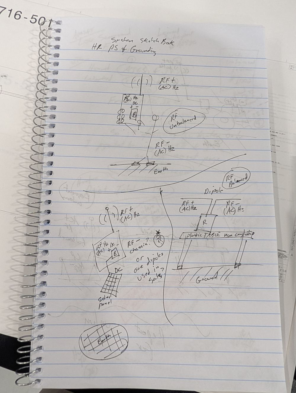
The two comparison diagrams above are drawn directly from Matthew’s own sketchbook (“System Sketch Book — HF PS & Grounding”), photographed 2026-07-22 and kept here for provenance. Several marks on these pages are Matthew’s own open questions to himself (e.g. “RF– chassis? or dipoles are used in ? systems”), not settled conclusions, and haven’t been silently resolved by guessing at handwriting — the resonant-coupling and RF-choke sketches in particular are still genuinely unexplained here and pending a fuller write-up.
See Practical Applications for the section this belongs to.